ransduction, in general terms, means to convert energy from one form to another. In terms of piezoelectric transducers, it means the conversion of electrical to mechanical energy and/or vice-versa. This can take place in a variety of mediums (air, liquid, etc.) using a variety of transducer designs.
To simplify our discussion, we will break the anatomy of transducers down into two main categories: single element transducers and multiple element or pre-stressed stack transducers. In this newsletter, we will be discussing the anatomy and considerations of single element transducers.
Single element transducers are often the most cost effective solution, especially when experimenting with transduction for specific applications. By definition, single element transducers contain one active ceramic element, fewer than the multiple element or pre-stressed stack transducers. This often results in a reduced cost and simplicity in design. They can be easily designed as transmitters, receivers, transceivers, etc. Applications for single element transducers include medical, therapeutic, NDT (non-destructive testing), flow/level sensing, air transduction, distance measurement, fish finding, etc. APC specializes in custom single element transducer design. If you have an application that requires custom single element transducers, contact APC today to discuss your requirements.
Single element transducers are made up of 4 primary components, the piezo-ceramic element, the backing layer, the matching layer, and the housing/cable assembly as seen in figure 1.
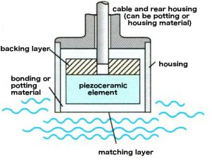
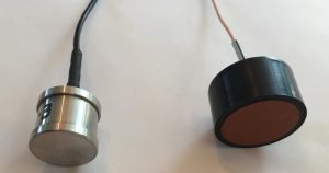
Figure 2 shows two examples of single element style transducers custom built at APC for various applications. It is easy to see the difference in the housing, the cable, and the matching layer materials but the similarities in basic design.
Let’s discuss the considerations regarding each primary component and the purpose they serve in the transducer starting the the piezo ceramic element:
In a single element transducer, the ceramic element generates or receives the pulse and often operates at resonance. This simplifies the design and optimizes the performance. The ceramic element can also help determine the physical size of the transducer and its housing. When choosing a ceramic element, start by thinking about what it is you are trying to accomplish. Whether transmitting, receiving, a simple pulse echo, or a complex crack detection, the application dictates the power requirements and beam angle, therefore setting the PZT material composition requirement (hard for high power applications vs. soft for low power and sensing applications) and physical size (physical size sets frequency and beam angle).
If you have selected a ceramic element based on the criteria above, it may be time to choose a housing. The design of the housing is driven by the final application of the transducer and the size of the ceramic element required to meet the needs of the application. Where does this housing have to go? How will it be mounted or integrated into a system? What might it be exposed to? (environments, chemicals, gases, temperatures, etc.) Are there regulatory requirements such as in the medical field? Will a portion of the housing also be utilized for electrical connections? Common housing materials can be various types of aluminums, stainless steels, plastics, or other composite materials. Once you have selected a housing material and design, its time to begin the process of selecting backing and matching layers.
The purpose of the matching layer is to provide a material “buffer” from the acoustic impedance of the ceramic element to the acoustic impedance of the medium which the generated signal will be travelling through. The acoustic impedance of a material is defined as the density of the material times the speed of sound of the material. If the acoustic impedance mismatch is small enough, a single matching layer can be used. However, if the acoustic impedance mismatch is large, several matching layers may work together to gradually transition from the impedance of the ceramic to the impedance of the target medium. Generally speaking, the higher the number of iterative steps in the matching layer and the closer the final match to the target medium, the higher the efficiency. Single matching layer efficiency can be in the range of 10-50%, while multiple layers can increase that efficiency by 25% or more.
Also important is the speed of sound of the material used for the matching layer. It is very common to utilize matching layers in ¼ wavelength increments to additionally enhance transmission efficiency and promote operation at resonance.
In simple terms, the backing layer is a highly attenuative layer designed to direct energy out the front of the transducer and eliminate energy loss from the backside of the ceramic. The backing layer can be made of various materials, including air. Backing materials can also be used to control pulse resolution, at the expense of transducer efficiency. When choosing a material for backing a transducer, it is important that the density be high for the purpose of acoustic impedance matching of the ceramic element, but the layer must also be attenuative. When backing with air, the thickness of the air layer is not critical, however if backing with another material the thickness will need to be determined by the material properties, density, and attenuation. A properly selected backing layer with high acoustic impedance can increase the transducers signal quality by absorbing and damping the back end signal from the ceramic element.
If backing with air and potting the transducer, an air substitute must be used as a placeholder and is often made up of very specific foams or cork materials.
So often overlooked but a critical part of the transducer, the cable assembly must be able to withstand the same environment as the transducer and have, in most cases, custom connectors to interface with the system for which it is being designed. It can be sealed through the housing, potted into the back of the transducer, have custom insulation, custom connectors, etc.
APC has considerable experience designing, supporting, and manufacturing custom single element transducers for many, many, varied applications. If you have any questions, an application to discuss, or a design to review, please contact APC International today!