To understand the poling process, a basic review of the crystal structure is helpful.
Typical PZT materials exhibit a perovskite structure. One can visualize this structure as a cube with eight large lead (Pb) ions at the corners of the cube. Six oxygen (O) ions are situated one in the center of each of the six faces of the cube, and their configuration forms an oxygen octahedron within the cube. The zirconium (Zr), titanium (Ti), or other ions are located in the center of the cube and coincidentally in the center of the oxygen octahedron. See figure 1 for a graphical representation of the PZT unit cell in a cubic state, above its Curie temperature.
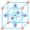
Figure 1 : PZT unit cell above Tc. The red spheres represent Pb, the gray spheres represent O and the tiny black sphere in the middle Ti, Zr
Crossing below the Curie temperature, the material undergoes a phase transformation to tetragonal allowing for polarization. In the tetragonal cell, the cube is slightly elongated, with the Ti or Zr ion no longer sitting in the middle but slightly offset instead. See figure 2 for a representation of the tetragonal cell:
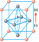
Figure 2 : PZT unit cell below Tc. Notice the slight elongation of the cell and the existence of a dipole resulting from the offset Zr, Ti ion
The key to the polarization of PZT materials is the position of the central Zr or Ti ion in relation to the oxygen octahedron. The space within the octahedron is fairly large, and both the Zr and Ti ions are comparatively small allowing for some movement of the Zr or Ti ion within the octahedron. This flexibility results in the central Zr or Ti ion “favoring” a particular position in the octahedron, lowering the overall energy in the system and causing a polarization in a given direction. There are several possible polarization directions in the octahedron for a given polarization domain, usually designated, in degrees, at 90 or 180.
In unpoled PZT material, all of the inpidual polarization directions form areas of similar polarization directions called domains, and the domains are randomly oriented and “cancel each other out” leaving no net polarization for the component (figure 3).
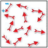
Figure 3 – Random orientation of polar domains resulting in no net polarization
The poling process itself involves applying a high DC electric field to the components for a specific length of time while the part is held at a given temperature. Typical DC voltages are on the order of 2000 volts per mm of component thickness. The effect of elevated temperature, usually resulting from performing the poling process in a heated dielectric fluid bath, is to make it easier to “switch or align” the domains. See figure 4 for a representation of aligned domain. during and after the poling process.
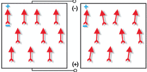
Figure 4 – Left: domain alignment during the poling process while voltage is applied. Right: remanent polarization after process is complete and poling voltage is removed
The result of the poling process is mostly oriented domains and a net polarization in the direction of applied voltage. The degree of polarization obtained is measurable by the (d33) and the delta F, which is the difference between the resonant and the anti-resonant frequencies as measured using an impedance analyzer. The larger the value of (d33) and delta F, the more efficient the material is at changing one form of energy into another i.e. mechanical energy to electrical energy or vice-versa. Small changes in the poling parameters (temperature, time, field strength, etc) can result in small changes in the measurable properties of the finished component.
Because the poling process is not a permanent one, the slow regression of aligned domains toward random orientation occurs in all PZT materials. This is measurable and is represented by the change in properties in percent per time decade. Therefore the apparent stability of the PZT material seems to increase with increasing time. For example, after poling, a property such as dielectric constant (K) may age -3% in the first day, -3% over the following ten days, -3% over the following 100 days, etc. Aging rates are not consistent from PZT material to material, with hard PZT materials typically aging at a faster rate and soft PZTs generally aging at a slower rate, comparatively.
External and internal stresses can lead to depoling or advanced aging of the PZT material. External stresses such as thermal stresses, excessive mechanical force resulting from mismatched bonding systems, excessive voltage application all can result in internal stresses. The effect of these stresses can also be cumulative. Combinations of stresses can reduce the overall stress threshold for depoling.
All of the factors discussed above must be taken into consideration when designing PZT components or mechanical/electrical systems for PZT components..APC may be able to help you when incorporating PZT materials into your systems.
For additional information or for technical assistance please contact your sales associate or visit www.americanpiezo.com
Mark your calendars for next months issue: Testing, Inspecting, and Packing PZT Materials!
Read More On Piezo Applications
What is the Purpose of a Piezo Motor
Piezo Aiding Advancements in The Healthcare Industry