In our last several articles we have been delving into the anatomy of single and multiple element transducers as part of our “After Manufacturing” series of articles written to explore the multiple uses for piezoceramics once they are manufactured. Over the next several issues, we will explore some individual transducer styles and applications, starting with the most common, air transducers.
A day doesn’t go by that you don’t encounter an air transducer in every day life. Being able to transmit and receive ultrasonic signals through air makes air transducers some of the most common types of transducers used day to day. From distance measurement and object detection (think automotive proximity sensors) to medical flow sensing, bin level measurement, and even high tolerance wind speed measurements (anemometry, time of flight or Doppler) air transducers are all around you. There’s no escaping it, so why not understand it!?
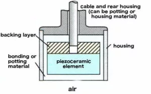
Standard air transducers are of the single element style (see figure 1) and operate at several “general” frequencies, the most common of which are 25kHz, 40kHz, and 300kHz. The higher the frequency, the higher the measurement resolution (at the expense of measurement distance). Higher frequency air transducers are generally useful for high resolution measurements at distances of 1.5″ – 10″, while some lower frequency units could measure fairly accurately at ~20 feet with adequate resolution. APC is proud to offer a 300kHz air transducer/driving circuit package for experimentation and measurement. Please see the APC website for more information. As with any system for transduction, beam pattern, power, and signal post processing techniques play a very large role in the accuracy, resolution and useful measurement distance.
When considering air transducers for a specific application, one may run across “transmitting” air transducers and “receiving” air transducers. They operate at slightly different frequencies to optimize efficiency. In a very basic sense, when measuring distance, level, or detecting objects, a “transmitting pulse” is generated and directed towards a target. The signal travels through air, is reflected off the target and directed to the receiver. By measuring the time of flight of this “pulse” from transmitting to receiving it is possible to determine distance, proximity, level, presence of an object, etc.
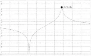
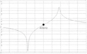
When transmitting, it is most common to operate the air transducer at its frequency of minimum impedance, or resonant frequency (Fr). See Figure 2. Transmitting at this frequency generates the highest output signal for the input power applied and is therefore the most efficient driving condition. When using an air transducer in a receiving application, it is more efficient to receive signals at the frequency of maximum impedance, or anti-resonant frequency (Fa). See Figure 3. This condition maximizes the signal generated by the transducer as the result of a mechanical stimulus, or incoming acoustic signal. The result? 40kHz air transducer transmitters operate at Fr=40kHz, while 40 kHz air transducer receivers operate at Fa=40kHz.
 |
 |
These optimized conditions are great, if there is enough space for dedicated transmitting and receiving transducers, but this is often not the case. Therefore, air transducer “transceivers” are also fairly common. In a “transceiver” application the air transducers Fa and Fr frequencies are centered around the 40kHz operating frequency, and drive circuits and signal post processing techniques can fill in the gaps resulting in perfectly useful signals for many applications. See Figure 4.
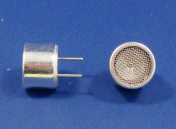
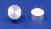
Physically, air transducers are generally available in “open face” or “environmental” enclosures. Open face transducers generally are open to the atmosphere, are more efficient (not having to transmit through a housing), and often contain a focusing cone to assist in beam development and accuracy. See Figure 5. Environmentally packaged air transducers are sealed to the atmosphere, ideal for damp or harsh environments, but operate at reduced efficiencies as a result of the housing material. See Figure 6. Common housing materials are various types of metal including aluminum and stainless steel, or plastics, depending on the environmental requirements.
APC offers standard piezoelectric air transducers that contain a piezoelectric ceramic element that is mounted in an aluminum, plastic, or environmental housing and are available for quick delivery! Our air transducers are available in 25, 40 and 300 kHz signal frequency.
Air Transducers from APC provide:
APC offers stock air transducers that are:
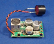
In addition to standalone air transducers, APC is also proud to offer a 300kHz air transducer/driving module combination. See Figure 7. This combination can be used in a variety of applications including:
See Spec Sheet 10-3300 (air transducer and module combination)
Don’t see a standard air transducer that will work for your piezo system? APC also offers custom designed air transducers!
To place an order for APC’s in-stock standard air transducers take a look at our website. If you don’t see what you need, contact any sales representative or request a quote to discuss your custom needs.