Last month, we discussed briefly transduction in general and the anatomy of single element transducers and their applications. This month, we will be movin.on to multiple element transducers.
Where single element transducers are cost effective, useful for low power applications, operate at the ceramic element’s resonance, and are easy to drive and experiment with using basic equipment, multiple element or stack transducers are really custom designed for high power applications.
In a multiple element or stack transducer, the entire transducer assembly becomes one mechanical system, with its own resonance, typically in the 20 kHz to 100 kHz range. This means that the ceramic elements are generally NOT operating at resonance, but are acting as a driver to induce resonance in the entire mechanical system.
The multiple element, or stack transducer, is assembled primarily of five components, as seen in figure 1. A front mass, multiple ceramics, shims to make electrical connections, a back mass, and some way of assembling and pre-loading the stack, typically a bolt.
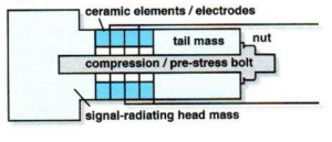
Figure 1 illustrates the 5 primary components of the stack transducer
The Front Mass
The front mass is the business end of the transducer. Ideally, a majority of the power generated by the transducer is directed through the front mass. This is achieved by utilizing materials, generally metal (aluminum, titanium, etc.) which is lower in density and lower in acoustic impedance than the back mass.
The Back Mass
In order for the transducer to operate as expected, the back mass must be a material of higher density and higher acoustic impedance than the front mass in order to direct the generated energy forward, to the front mass.
The Ceramic Elements
The number, geometry, and arrangement of the ceramic elements helps to define the transducers displacement, power output, and operating frequency (frequency is really a combination of mechanical system properties and ceramic element properties).
The orientation of the ceramic elements is critical, as the physical displacement of the ceramics should be maximized. To achieve this, it is common practice to arrange the elements mechanically in series, but electrically in parallel as seen in figure 2.
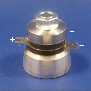
Figure 2: Stack transducer with two rings mechanicallyoriented in series but electrically wired in parallel. In this case, the end masses also act as a (-) reducing the need for an extra shim.
Traditionally, the ceramic elements would be driven in their radial mode inducing a diameter, and therefore also a thickness, dimension change thereby driving the mechanical system.
The Shims
The shims provide an external electrical connection as seen in figure 2. Typical shim materials include brass, copper, stainless steel, or beryllium copper. They should be flat, hard, have high electrical conductivity, and provide a path for heat conduction (to help dissipate heat from the ceramics to the masses).
The Bolt
Sounds simple, but is very critical in the assembly of the transducer. The bolt must be made of a material with relatively low coefficient of thermal expansion. This is to prevent the loss of pre-stress while the transducer is operating and producing heat. Typically, these bolts would be torqued to about 30 lb*ft, but with experience and standardization the electrical output of the transducer during the pre-stressing process can be used to determine the final torque.
To compliment these 5 basic components, the addition of a custom front mass, front mass assembly, or amplification horn can increase the transducers output tremendously.
Applications for these high power transducers include:
APC International is proud to offer several standard power transducers as stock items for quick delivery..More information, along with additional technical resources, can be found in the Ultrasonic Power Transducer section of the APC website..Please visitwww.americanpiezo.com for a variety of standard ultrasonic power transducer assembliesfor use at various frequencies, or contact APC for information regarding custom assemblies for specific applications..For ultrasonic cleaning applications, APC is also your source fo.Ultrasonic Power Generators..
APC International can custom build power transducers using components and powders made right here in the USA. Visit our custom piezo materials page an.begin by choosing the right piezo material for your application.
What is the Purpose of a Piezo Motor
Piezo Aiding Advancements in The Healthcare Industry