Good quality electrical connections are absolutely essential to device performance and longevity. The engineering and technical assembly staff at APC International are experts at terminating connections to PZT and we are willing to share our expertise and accumulated knowledge and experience if necessary so please contact APC International with questions or for a review of your termination process.
There are several different methods one can utilize to make electrical connections to PZT components, and generally it starts with the electrode material on the PZT component and any special patterns or custom poling techniques. Read on for a breakdown of the major considerations when connecting to PZT.
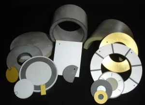
When ordering custom PZT ceramics, the end use is always at the forefront of the discussion. Typically, the required connection method naturally develops as a result of the type of end use, the housing, the exposure, etc. With this in mind, it is common to specify custom electrode patterns to make connecting to the PZT easier. This may include a side tab, a wrap-around electrode, custom electrode “pad” areas, etc. Figure 1 illustrates several different electrode pattern styles. For a more detailed summary of electrode patterns, please visit the APC website by following the link Piezo Electrode Patterns.
APC also offers several “standard” electrode options to which the connections may be different. Fired on silver is the electrode of choice for most people. It’s cost effective, relatively easy to work with, and is easily solderable. For shear mode applications and select other custom applications, a heat cured silver epoxy is the best choice. This material is NOT solderable but leads can be bonded to the surface using similar silver epoxies. Lastly, nickel plating is a robust surface, can withstand certain extreme environments, and is solderable using the same techniques one would use when soldering to the standard silver electrodes.
While considering the end use, housing, electrode pattern for ease of connection, etc. one must also ask, “How exactly are we going to make this connection to the piezo?” The answer may depend greatly on several factors including part size and geometry, accessibility inside the housing, the environment involved, the shear volume of the parts in consideration (avoiding something like soldering when connecting to 1 million piezo elements would be beneficial both in cost and time) etc. Another question you might ask could be “Do we need wires to make this connection?” Connecting to the piezo can be as simple as bonding it to a conductive substrate using a conductive adhesive of some type, simply soldering wires, bonding leads using conductive silver epoxy, or as complicated as custom designing housings with electrodes inside using housing force to hold the piezo between two metal electrodes. We will briefly touch on each.
Solid? Stranded? Gauge? Insulation type? Intrinsic Safety? So many things to consider when thinking about selecting a wire for your application. APC recommends the use of stranded wire for most applications. This is due to the improved flexibility and higher conductance when compared to solid core wire. When working with smaller PZT components (OD < .5″ & Thk < .040″) using typical power levels, lead sizes of 28 to 32 are typical. For intrinsically safe applications, this may need to be increased to 26 gauge. As the components get larger or the required power levels increase, 26 gauge, and even 24 gauge, may be used. For applications where power requirements are small, or the components are very thin, a lead size of 32 gauge is the preference at APC.
The wire insulation material is also something to be considered. APC typically uses PTFE or PVC wire insulation when attaching leads to components. PVC is more flexible and will bond to most potting materials (see APC recommended epoxy materials) but does not have the chemical or temperature resistance of PTFE. PTFE is slightly less flexible, more chemical and temperature resistant, but may not bond to potting materials unless chemically treated beforehand. Each has distinct advantages and disadvantages. Contact your APC representative to discuss options.
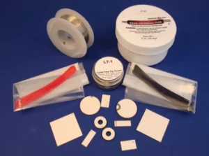
Soldering is the most straightforward way to connect a wire to the component. The fired on silver coating as well as the plated nickel coating supplied by APC are solderable in the same way. APC’s Lead Free Solder Options found on the website is a great introduction to different types of solder for RoHS applications, our Soldering Instructions will guide you step by step through the process, and our Soldering Kit (figure 2) that includes all of the things (with the exception of a soldering iron) that you need, all combine to ensure success.
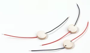
In addition to the resources above, solder dot size and location play a role when connecting to piezos. Generally speaking, using the smallest gauge wire possible results in the smallest solder dot possible. This reduces the chances of “damping” the components response. The location of the solder joint can also affect the response of the component. Keeping the solder joint as close to the edge of the component as possible (figure 3) reduces the “damping” effect, while placing a large solder joint near the center can accentuate that same effect.
As simple as it sounds. Choose an appropriate conducting, silver containing epoxy and apply to the wire and the component. Simple fixturing may be required to hold the wire in place throughout the curing process. Pay special attention to the curing profile when choosing an epoxy material. Curing profiles should not exceed approximately one half of the curie temperature of the material or de-poling may occur. Using a bonding technique without a wire is also possible if the substrate or housing to which the component is being bonded is, or has, a conductive portion. An example of this would be a plastic housing with electrode “pads” molded directly into the housing. Connections can then be made to electrodes separate from the ceramic component, inside or potentially outside of the housing.
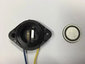
It is also possible to make connections mechanically using electrode pads formed into housing combined with a second electrode contact which can be pressed against the component with force. This can be accomplished using a housing cap, spring loaded contacts, etc. (figure 4). It is best to combine this method with some type of bonding and potting to ensure long term contact is maintained.
As you can see, there are several useful techniques, or combinations of techniques, making electrical connections to PZT components. Please contact APC with questions or comments, and when in doubt, leave it to the experts!! Contact APC for a quotation for lead attachment or assembly services!