Taking the mystery out of firing profiles
Jason Getz, Process Engineer
Brian Julius, V.P. Manufacturing / Materials Engineer
Ron Staut, V.P. Technology
Once the PZT components have been pressed into green shapes (~60% dense), they are prepared for Binder Burn Out (BBO). BBO is one of the most critical process steps in the manufacture of PZT ceramics. As discussed in previous articles, organic additives (binders and plasticizers) are added to the PZT powder during the powder manufacturing process to give the PZT powder cohesive and plastic characteristics, allowing the powder to be pressed and formed into bulk PZT ceramic shapes. BBO is the process of removing these binders, plasticizers, and other additives via either combustion (in air), or pyrolysis (in nitrogen). For the sake of this discussion, we will only focus on the removal of binder via combustion.
Before attempting to remove the binders via combustion, it is important to have a basic understanding of how the binder systems function. Some of the most commonly used binder systems are based on polymerized precursors, or polymerized vinyl monomers. These polymer binders consist primarily of small polymer particles, or chains, varying from 20-600nm in length. These polymer chains coat the surface of the PZT ceramic particles and “bind” them together by interlocking chains during pressing, thereby keeping the compressed powder shape and providing durability when handling the green ceramic. Two examples of commonly used polymer binders are polyvinyl alcohol (PVA) and polyvinyl butyral (PVB). In custom applications, poly-acrylates (water based acrylic polymers in hindered amine groups) can also be used. In addition to the polymer binder, plasticizers play an important role in the binder system and are added at approximately a 60:40 weight ratio (60% polymer binder: 40% plasticizer) to improve flexibility and increase durability of the pressed component while lowering the glass transition temperature (Tg) of the binder system.
The binder system behavior versus temperature can vary greatly depending on its molecular weight and percent hydrolization, the molecular weight of the plasticizer, and the amount of the plasticizer in the system. Moderate to high molecular weight binders are typically stronger, display higher tensile strengths, and increased component durability while handling. That said, the highest molecular weight binder might not result in the best PZT component yield. As a rule of thumb, when polymer chain length increases, molecular weight increases, component green strength increases, and as a result the thermal energy required to combust the binder/plasticizer system as well as the amount of combustion products generated during BBO increase as well.
Before designing a furnace profile to remove these binders via combustion, it is critical to understand the physical characteristics of the binder system and exact behavior of the binder in a PZT component under applied thermal stress. This can be determined via thermo-gravimetric analysis (TGA) and differential thermal analysis (DTA), and the data obtained from these tests can be used to design a furnace profile unique to the binder system being used. The DTA measures the amount of thermal energy absorbed (endothermic), or generated (exothermic), by the chemical reactions occurring during the heating cycle. TGA measures changes in the weight of a sample in response to increasing temperature. By graphing % weight loss vs. temperature (thermo-gravimetric curve) and change in sample thermocouple output (deltaT) vs. furnace temperature, a basic guide or outline can be formed on which to base an engineered, composition specific, BBO profile (see Fig. 1 – TGA/DTA example for representative sample of PZT bulk component (RT to 1200C @ 10C/min in Flowing Air).
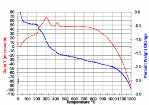
Typically, temperature ranges that show high weight losses and/or large changes in sample deltaT are approached at a slower ramp rate (<50C/hr, the larger the change, the slower the rate). It is also good practice to soak the PZT components near the mean temperature of any identified critical range for 1-3 hours, depending on PZT component shape, aspect ratio, exhaust rate (airflow) and setter clearance. See Figure 2 -(typical BBO profile for removal of PVA: PEG binder solution) for a generic BBO profile corresponding to the TGA curve shown in Figure 1.

As the binder system combusts, the result is typically shorter polymer chains, small percentages of short carbon/hydrogen groups, water, cyclohexane, carbon monoxide, and carbon dioxide. These combusted, shortened polymer chains and binder by-products must escape the ceramic body by diffusion through open porosity, therefore controlling the rate of combustion is absolutely critical. If the products of binder combustion are being generated faster than they can diffuse through the ceramic body, internal pressure can build, ultimately resulting in micro-cracking, or worse, total mechanical failure of the ceramic component.
The required BBO profile varies with the geometry of the PZT body, but can be directly correlated to the ratio of surface-area:volume. The larger the ratio,the easier it is for combusted binder byproducts to diffuse through the material ultimately to be exhausted. It is for this reason that exhaust rates play a key role in the BBO process. To facilitate adequate BBO conditions, the minimum air refreshment rate for any BBO process should be > 1 complete air change every 15 minutes. It is also crucial that the air replenishment has not only an adequate rate, but also that the airflow is laminar, as laminar flow is much more efficient than turbulent flow.
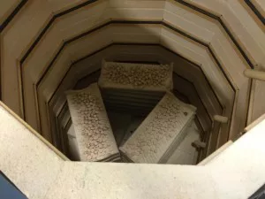
Once a profile is designed, PZT components are loaded onto setters, and stacked inside the BBO furnace (fitted with an exhaust fan, see Fig. 3 – PZT components, loaded on setters, and stacked inside a typical BBO kiln). The profile is then started, and allowed to complete its thermal cycle.
At this point, the PZT components are robust enough to handle, but still very fragile. They are carefully unloaded and neatly stacked in high purity alumina crucibles in preparation for sintering.
Solid state sintering is the final densification of the ceramic body. In a bulk PZT ceramic process, sintering occurs using heat as the primary energy source, and volume diffusion as the primary mechanism for material transport.
Since the energy required for sintering demands temperatures in excess of 1200 C, but the volatilization temperature of lead is only ~800 C, the parts are sealed in high purity alumina crucibles to prevent lead from escaping. Donor materials may be used in the crucibles to help build a partial pressure of lead thus further reducing lead loss from the components being sintered.
The driving force for sintering and densification, as it is for all reactions, is the reduction in free energy, which translates to reduction in surface area, thereby resulting in densification.
Reduction in porosity during sintering is also critical and occurs as a result of pore migration along grain boundaries to the outside of the component, and by the solid state movement of vacancies to the grain boundaries. It is through this process that ~60% dense, open pore structure green PZT ceramic is densified to >95% and exhibits closed pore structure and low overall porosity.
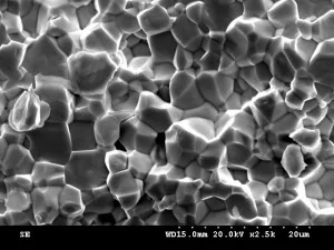
With 3-5um grain size being our ultimate goal (Figure 4 – fracture surface of sintered PZT ceramic showing 3-5 um average grain size), sintering temperatures range from 1240 C to approximately 1350 C. Soaking the ceramic at peak temperature from 2-6 hours helps ensure temperature uniformity, grain growth, and pore reduction.
When designing a furnace profile for sintering, it is important to consider the size and geometry of the component you are firing as to not thermally shock the material by ramping, or cooling, the furnace too fast. Dilatometry is a useful tool that measures the change in size of a pressed PZT sample when fired through the sintering range using a controlled furnace profile. By utilizing the data generated by dilatometric analysis, the shrinkage of the ceramic material throughout the firing profile can be documented and reviewed. Maximizing this shrinkage by altering firing profiles is a great starting point when designing furnace profiles for sintering PZT ceramics.
Once a profile has been determined, the components (sealed in high alumina crucibles) can be loaded into the high temperature furnaces and the cycles can begin. Typical firing cycles can range from 12 hours to > 100 hours depending on the size and shape of the components being fired. Once cool, the furnaces are carefully unloaded and ceramics are prepared for the next stage in the series: “Shaping and Machining Fired PZT Ceramics.”
For more information on pzt components and how they are used, contact one of our representatives today for more information.