Complex Design? Expensive Prototypes? You’re not alone. These are common dilemmas when designing active mechanical systems using piezo materials.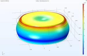
Displacement plot of PZT disk bonded to custom matching layer
Some conventional strategies to manage development cycle time and cost exist. Iterative or trial-and-error prototyping is a basic engineering strategy in which design, construction, and evaluation of a series of prototypes occurs in an iterative format, where each iteration is an attempted improvement upon the previous one. Unfortunately, this can be costly and very time consuming. Designed experiments, which involve pre-designed prototypes covering a wide range of variables, are constructed and evaluated together to predict the ideal set of characteristics for the product design. While this strategy can save some time by evaluating the prototypes in parallel format, it can be very costly to produce and evaluate the high number of prototypes required.
Finite element analysis (FEA) simulation is an advanced engineering strategy which utilizes software programs to analyze a potential design using physics-based calculations. This enables an engineer to “virtually” analyze several designs until all design requirements are met. At that point, only a very limited number of iterative design changes may be necessary to reach the final design. FEA simulations save valuable time and prototyping expenses by reducing the amount of physical prototyping to a fraction of what it would be with other development strategies. The drawback of FEA simulation, however, is that the software and computer hardware can be extremely costly.
Finite element analysis (FEA) software utilizes a mathematical technique called the Finite Element Method (FEM), as described in the following. A physical design geometry – modeled in a 3D graphical interface – is separated into nodes and elements (or points and lines). This represents the physical design as a complex “wire mesh” rendering.

Mesh of a PZT disk geometry, including nodes and elements.
Physical coordinates are assigned to the nodes and elements, creating a large numerical matrix. Material properties and initial conditions are assigned using the graphical interface. Equations representing the desired physics (Piezoelectricity, Structural Mechanics, etc…) are generated and computed. The result is the predicted physical behavior of the geometry and conditions being simulated. This solution is post-processed to be represented both graphically and quantitatively.
Simulated outputs for PZT applications commonly include:

Displacement and mode shape plot of a PZT disk
These examples only scratch the surface of the possibilities of FEA Simulation. Individual elements to transducer subassemblies to entire product assemblies can be analyzed via simulation.
APC has been making investments in FEA simulation software and hardware. These investments have already begun to support APC International internally, as well as improving the customer experience through technical collaborations. APC is still refining simulation accuracy by incorporating actual test data from our APC materials manufactured in-house. While we are not yet in the position to offer modeling as a paid service, we have been collaborating with our customers on new designs, new products, and even the improvement of existing products. Our efforts in this area will continuously improve our ability to provide exceptional technical service and support to our customers and to continue to add value to our products and services.
Please contact the APC team for more information regarding FEA Simulations.
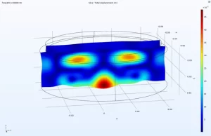
Cross sectional (slice) displacement view of transducer consisting of piezo disk and custom matching layer.