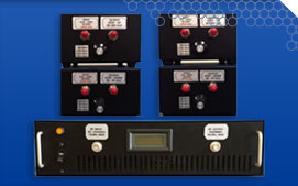
Amplifiers
When powering a piezo device, it is important to briefly review the frequency ranges in which they operate. Generally speaking, we can simplify frequency categories down to 2 and consider a piezo device either a “Low Frequency” or a “High Frequency” device. A low frequency piezo device would typically operate from direct current (DC) to approximately 100 kHz, while a high frequency piezo device would operate from approximately 100 kHz to 20 MHz.
This is a rough breakdown of some typical devices and the frequencies where the operate:
| Device Type/Family | Approximate Ref. Frequency Range |
| Acutators | DC through ~3kHZ |
| Buzzers/Speakers | ~3 kHz through ~10 kHz |
| Speakers | 100 Hz through 20 kHZ |
| Ultrasonic Cleaning/Welding | 20 kHz through 100 kHz |
|
Medical, NDT, Nebulizers, etc. |
40 kHz through 5+ MHz |
Powering a piezo device is not complicated. Shown below is the flow required to be successful in driving a piezo device.
![]()
Input Signal:
The input signal is simple. Create a signal at the frequency for which the piezo device was designed to function. This can be done with a frequency generator, waveform generator, oscillator, or even a computer with a USB adapter. Once you have a signal, it must be amplified to a power level adequate for driving the piezo device.
Power Amplifier:
In a typical power amplifier, your signal input is directly and fully amplified (all 360 degrees of the input cycle) and delivered as a higher power output with good signal quality and little distortion.
Impedance Matching Circuit:
Impedance matching circuits may or may not be necessary, depending on the frequency of the device you are driving. Low frequency piezo devices (DC to 100kHz) are often used in non-resonant applications. Additionally, power amplifiers in these ranges are typically not load dependent and are designed for impedance mis-match. The impedance of the piezo device (load) in this case does not dramatically affect the amplifiers performance.
Driving high frequency piezo devices (100 kHz – 20 MHz), on the other hand, requires precise matching of the device impedance to the amplifier output. This can be achieved to an acceptable degree of accuracy using an adjustable impedance matching device or by designing a custom matching circuit.
APC is proud to offer a line of SVR amplifiers for powering actuator devices (DC-1 kHz), RF amplifiers for higher frequency devices (20 kHz – 12MHz @ 100W) and impedance matching boxes to take the mystery out of powering piezo devices. Custom power amplifiers are available through APC by request. APC is currently offering like new-used stock of several High Power LE Amplifier Systems but stock is limited so order soon!!! Contact your APC Technical Sales Representative with any questions, comments or requests.
SVR Amplifiers (Analogue)
| APCI Catalog No. | Type | Voltage Range | Input | |
|
SVR-150/1 SVR-150/3 |
Single Channel Triple Channel |
-30V to +150V (semibipolar) | ±5V (±10V with attenuation) | Spec Sheet |
|
SVR-200/1 SVR-200/3 |
Single Channel Independent Channels |
-50V to +200V | ±5V (±10V with attenuation) | Spec Sheet |
| SVR-150bip | Step Up | 500kHz to 5MHz | 200W | Spec Sheet |
RF Amplifier-BA12200L
| APCI Catalog No. | Type | Frequency | Power Output | |
| 90-4493 | Solid State MOSFET | 20kHZ to 12 MHz | 100W | Spec Sheet |
LE Amplifier-LE-150/200/3 (Like new-used)
| APCI Catalog No. | Type | Power Input | Power Output | |
| 90-4480 | 3-Channel | +/- 5V (+/- 10V) | 10V to +150V | Spec Sheet |
Impedance Matching Transformers
| APCI Catalog No. | Type | Frequency | Max Power | |
| 90-4495 | Step Up | 500kHz to 5MHz | 200W | Spec Sheet |
| 90-4496 | Step Down | 500kHz to 5MHz | 200W | Spec Sheet |
| 90-4497 | Step Up | 20kHz to 1MHz | 200W | Spec Sheet |
| 90-4498 | Step Down | 20kHz to 1MHz |
200W |
Spec Sheet |
| 90-4501 | Step Up | 20kHz to 1MHz | 200W | Spec Sheet |
| 90-4502 | Step Down | 5MHz to 10MHz | 200W | Spec Sheet |


